|
| ||
Dismantling a Power Supply Unit for Parts | ||
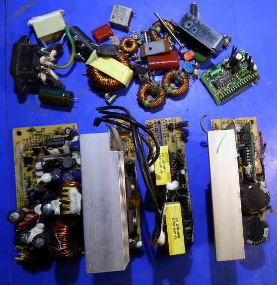
| A computer power supply unit will eventually fail. As it contains many electronic components that might be useful for your Electronics hobby, it can be worhwhile to dismantle it. Remove all screws and extract the fan, power socket and Printed Circuit Board assembly. Desolder whatever components can easily be removed. | ||
|
| ||
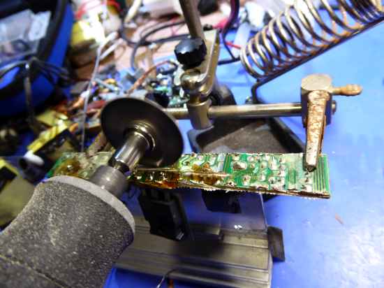
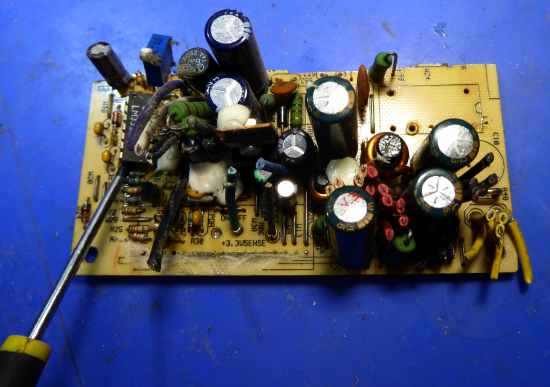
| With large heatsinks in the way, it can be impossible to remove many of the components. My method is to saw the PCB into strips, as shown above, I use a "Dremel" tool with a circylar saw blade (see photo below) but it's possible to use a hacksaw. Since the PCB materials can be hazardous, you should wear a mask and goggles that are suitable for protecting you from the dust. | ||
|
| ||
| I recommend using a large, "chisel tip" soldering iron bit, with temperature set to 430°C. Flood the area with flux. You'll find that some components can't be desoldered no matter how hot your soldering iron because the copper tracks soak away the heat too quickly. My solution is to saw through the copper tracks adjacent to the component pads. | ||
|
| ||
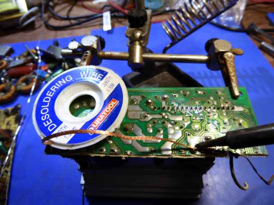
| Add 60/40 tin-lead solder to each joint. This solder melts at a lower temperature than non-lead solder and is much easier to remove. I use braided copper to soak away the solder. This has a small amount of dry flux embedded in it but that'sw rarely enough so add more. Press the soldering iron tip down onto the braid and hold it on the soldered joint. Wiggle the tip until the solder is removed by the braid. | ||
|
| ||
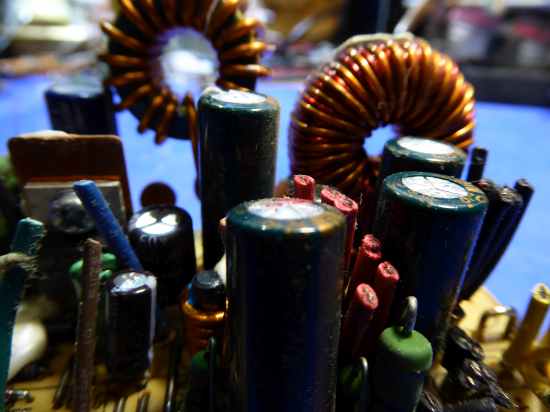
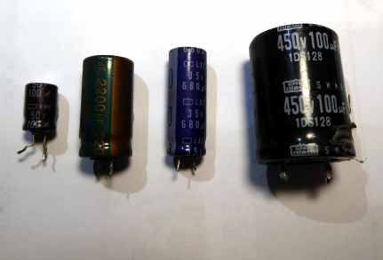
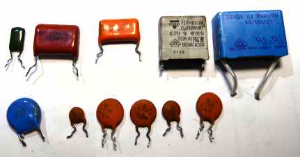
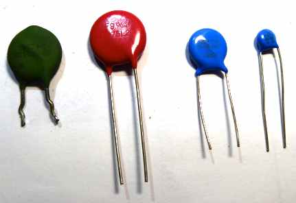
| Electrolytic capacitors with bulging tops like these (above) can be thrown away. | ||
|
| ||
| If you want to salvage a DIL (dual in line) I.C. (Integrated Circuit), remove the solder from every pin, as above, then carefully lever the I.C. upwards by inserting a flat-bladed screwdriver under each end in turn. | ||
|
| ||
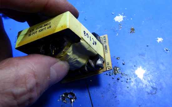
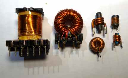
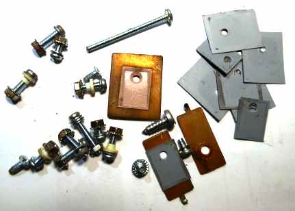
| Transformers can be sawn away with an oblong of PCB attached. Apply fresh tin-lead solder. Then heat each joint to melting point and immediately tap the assembly on the bench. Be very careful to prevent solder splatter from damaging you or your clothes! The remainder of the solder can be removed with desoldering braid, as described prviously, then the transformer can be pried away from the PCB. | ||
|
| ||
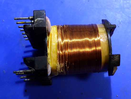
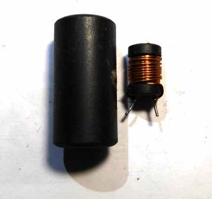
| The iron-dust core can be cracked away and you'll be left with a bobbing of useful enamelled copper wire that can be used in a project such as a crytal set radio. If you have questions, you can join the DIY UK HOBBY ELECTRONICS group on Facebook and ask away! | ||
|
| ||
|
| ||
|
| ||
|
| ||
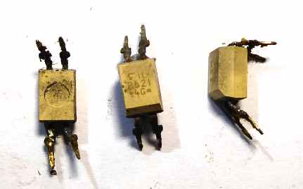
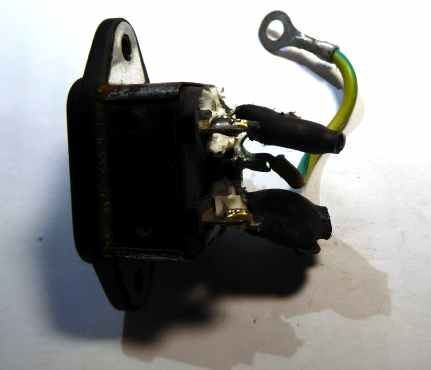
| Recitifiers (diodes). The largest in the picture is a package, which contains two rectifiers with cathodes connected to the centre pin. | ||
|
| ||
|
| ||
|
| ||
|
| ||
|
| ||
|
| ||
|
| ||
|
| ||
| Send this page address - CLICK HERE - to a friend ! | ||