|
| ||
|
CAR ALTERNATOR DEVELOPMENT 1964
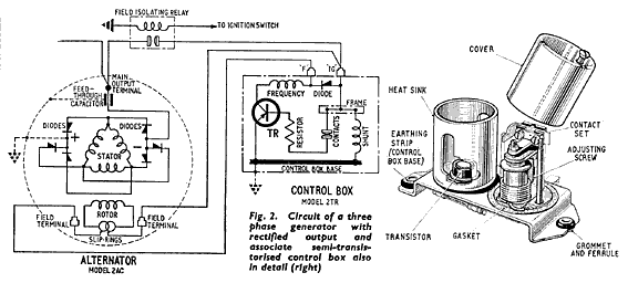
ALTERNATOR OUTPUT CONTROLSThe only form of control of alternator output required is one which will maintain the terminal voltage at a substantially constant predetermined value, that is, a voltage regulator. Hitherto, a vibrating-contact electromagnetic device connected in the field circuit had been employed for this purpose, while a later development was the use of a transistor to interrupt the field current, the vibrating contacts being connected in the base circuit, so breaking only a small current (Fig. 2)
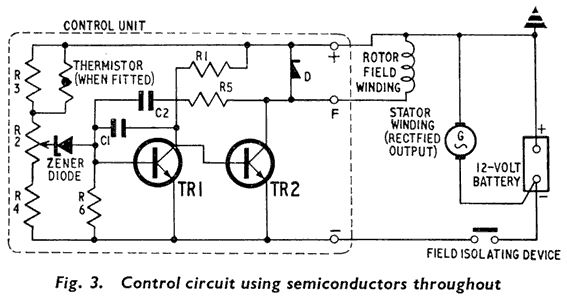
In each of these instances, the voltage reference ls provided by an armature tensioning spring. A further development takes advantage of the availability of Lucas silicon semiconductor devices to provide an electronic control in which all moving partsare eliminated; thus the control has increased reliability, since there are no moving parts to wear or to require adjustment, and this results also in greater stability in output control. In addition, the electronic control unit is reduced in size and weight.
The circuit of this control is shown in Fig. 3, and it will be seen that it contains a Zener diode and two transistors TR1 and TR2. In effect, the action is similar to that of the electromagnetic regulator in that the current in the alternator field winding is varied to maintain the generated output voltage within close limits, but switching is achieved by the transistors instead of vibrating contacts, while a Zener diode and potentiometer provide the voltage reference in place of the voltage coil and tension spring system. It is not proposed in this article to give a detailed description of how this control operates but, briefly, at rest or very low speeds the held circuit is completed through TR2 which is held conducting by virtue of the connection through R1. As the alternator rotor is driven at increasing speed by the engine, the rising voltage generated in the stator winding is applied to the potential divider consisting of R3, R2 and R4, and according to the position of the tapping point on R2, a proportion of this potential is applied to the Zener diode. When the value of this potential reaches the Zener diode breakdown voltage (corresponding to a known output terminal voltage) the diode conducts, and current flows in the base circuit of TRl . The latter becomes conducting, lowering the current in the base circuit of TR2 and, as a result, so also the alternator field excitation. Consequently, the alternator output voltage will tend to fall, and this in turn will reduce thebase current in TRI, allowing increased field current to flow in TR2. By this means, the field current is continuously varied to keep the output voltage substantially constant at the value determined by the setting of R2. Basically, this is the principle of operation of the Lucas Model 4TR Control, but there are certain desirable additions which are beyond the scope of this explanation. | ||
| Send this page address - CLICK HERE - to a friend ! | ||


