|
| ||||||||||||||
| ||||||||||||||

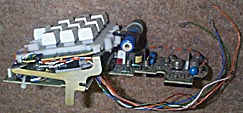
| Amongst my "claims to fame" were: Picture: Trimphone internal parts to replace rotary dial. What a bodge!! Yes, I designed this monster. |
|
The Trimphone was an abortion. It was designed for "occasional use" as a "bedside phone". You weren't actually meant to use it - let alone try to dial!! If you did, the phone simply wandered away from you. That's why they invented "Blu-Tack" - did you know? ;o)
The microphone was next to the earpiece and our acoustic designers, at GEC Telecommunications, tied themselves in knots trying to develop a plastic tube that would carry the sound from the mouthpiece up to the earpiece without sounding as if you were talking through a plastic tube. Of course this feat of engineering endeavour was doomed to failure before the P.O. "experts" even suggested it. Putting the nasty radioactive gas-filled fragile glass tube behind the dial was the "piece de resistance". A feat of stupidity that remains unmatched by anything designed subsequently by "The Post Office" as it was then. I believe the cost of disposing of those radioactive phials ran well into five figures if not six. Allegedly, they were all gathered together into one huge radioactive pile and kept there, glowing brightly for years, while the "experts" decided what to do with them.
Redesigning the phone to use a push-button dial seemed like a good idea at the time. The P.O. deemed that "the outward appearance shall remain the same". The designers at STC took that with a liberal pinch of salt and had a new top-cover moulding tool made (costing at least £20,000 in those days). The new cover was about 10 mm higher at the front and made the phone look like a brick.
Purely from a practical point of view (not aesthetic), I argued in favour of this approach at GEC and was told to pay for the new tool or shut up. I shut up and the existing moulding tool was modified by having an insert made to change it from a rotary dial hole to the 10 or 12 button "escutcheon" as it was called. The cost of this was only about £5000.
Unfortunately, this left me with less than no space in which to fit the push button keypad and electronics (see picture above) but I managed it anyway. We called it the "train board" because its profile was similar to that of a steam engine. At that time Surface Mount components were not in use and the circuit was fairly complex because it had to generate power supply voltages from the tiny current available from the telephone line, as well as requiring inductors for the tone generating circuits - two inductors were needed because the exchange used (and still does) a Dual Tone Multi frequency (DTMF) system.
Anyway, I designed an ingenious bracket and two Delrin mouldings to hold the keypad and board and a huge inductor thing that had something to do with current regulation (I think). This assembly had to fit over the lower telephone connection board which I redesigned slightly. When the cover was fitted, the whole thing bowed (but I didn't actually tell anyone). This was a design "feature" to keep the keypad pressed firmly against the top cover. That's my story and I'm sticking to it!
We had an order for 100,000 PB Trimphones so the whole development went at a crazy pace compared with the usual time scales. When my design finally reached the factory floor they discovered that it was impossible to fit the wiring loom in the 30 seconds allocated, so the factory managers, production engineers and shop-floor workers tore it apart and redesigned the wiring loom so it could be fitted more easily. Black mark for me and a slight delay in production. However, from that day on, the Director always greeted me by name when he passed me in the corridor on the way in from the car park. I like to think he realised I'd achieved the impossible in a ludicrous time scale but he probably just thought I was a young w*nker who'd almost lost him his job.
I was fairly p*ssed off when, less than a year later, the electronic boffins developed a tone-generating chip that needed no inductors. At the same time they introduced surface-mount components (although not on this design, as I recall). Anyway, the result was a keypad electronic assembly that was barely larger than the keypad mechanism itself. Fitting it into a Trimphone was a breeze but I don't recall if we actually manufactured any. I think the Trimphone project was dead by that time, anyway. Pity.
I don't remember any dates for this but the year of manufacture was stamped on the base of every GEC phone as, for example, "GEN73", where "GEN" was the three letter code allocated to GEC Telecommunications by "The Post Office" and "73" is the year.
One of my last responsibilities was the "GEC 2-16" (two incoming lines and 16 extension telephones) which was one of the first designs in which we were given a free hand by the (then) Post Office to make it as cheaply as possible. Previously, we had been bound by "P.O. guidelines" which restricted the way in which things could be designed. The 2-16 was the first GEC Telecomms design to use plastic pillars for PCB mounting. It was also the first in the world to use those reddish-brown Molex three-way sockets pushed onto the legs of TO220 regulators (my idea, subsequently copied by many others). It used 24 volt miniature relays and, at my suggestion, the "boffins" ran these off a holding-voltage of 12 volts to minimise power consumption. Whenever a relay was required to turn "on", the whole batch of relays was pulsed momentarily with a 24 volt supply. This was easy to do under microprocessor control. The unit used only a third of the power that had originally been calculated and it ran extremely cool compared with previous designs which had used 12 volt relays. The larger "5-20" had severe overheating problems to begin with. However, I got the cabinet manufacturers to make it with an inner mesh "roof" that let hot air rise while keeping bugs out (a design requirement). The actual cabinet solid "roof" was an inch higher than the mesh and was purely cosmetic, with slots at the rear and sides to let hot air escape. We managed to complete the design without needing to use a fan and the internal temperature rise with a 100 Watt power supply never exceeded 15 degrees C. This was quite an achievement. No fan meant lower cost, better reliability and no dust filters required.
I can't claim responsibility for all the innovations, however. A fellow worker called Gresham Clacy (Geophysicist) developed a modification for the flow-solder machine which vibrated the solder wave at around 230 Hz. The effect of the ripples was to allow flux gases to escape more easily and to provide more complete soldering of plated through holes in the printed circuit boards. Another company apparently copied the idea and made a much cheaper vibrator simply by using a mains-fed solenoid that ran at 50 Hz. I'm not convinced that the lower frequency was as effective since Clacy did extensive testing to find the optimum frequency. He also developed a way to run thermocouples with the board through the soldering machine and discovered major problems with the heat distribution across the boards being soldered. Again, his idea was copied by a company which, admittedly, made a much better device to pass through the machine than his "Heath Robinson" affair.
My very first design project at Aycliffe was the "Single Number Callmaker" or "Autodial 401A". The original Autodial was a large box full of cams, cogs and contacts. When you heaved down on the plunger it set a flywheel in motion that drove the various cams and cogs to open and close the contacts at 10 pulses per second. It could be "programmed" to dial out a complete telephone number of up to (I think) ten digits. My job was to design the base and plastic cover mouldings to meet the Post Office specifications. One problem was that it needed a hinged lid for access to the slide switch matrix but the Post Office boys did not want any visible hinges. It took me six months to develop an ingenious plastic spring hinge made of acetyl copolymer ("Delrin") to do the job. I imagine the total development cost was astronomical and I think we eventually manufactured just a few thousand. By that time, push-button "MF" (tone) dialling phones were on the drawing board and the Autodial was obsolete. 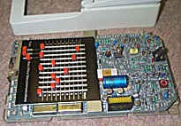
This electronic replacement "Autodialler" derived all of its power from the telephone line. The required digits were set by means of a slide switch matrix designed by the "Mechanical Department" (Godfrey Hall) under John Leworthy. The electronic circuit design was by, as I recall, "Sparky Bob" Stevenson and Maurice Weeks in the Electronics Design department run by (Stephen) "Sam" Crooks. A custom I.C. was designed to control the operation of the two mercury-wetted relays whose job it was to "loop the line" and provide the pulses. The I.C. was horrendously expensive to develop and produce. A ferrite transformer oscillator was employed to take the small current from the telephone line and convert it to a stable voltage supply.
Push-button telephones were a much better money earner for GEC. I had to source most of the parts and I recall phoning a company for a quotation for "one hundred- and five hundred- thousand" ceramic resonators - Murata I think it was. The sales girl repeated "one hundred and five hundred?" when I asked for a price
"That's thousand" I emphasised.
"Thousand? You mean, like, half a million???"
"Yep".
"Ah, I'll get the Director to call you back. We may need to build a new factory."
There are so many amusing stories about GEC. Like the time one guy called "John Thomas" left a small wall-mounted office telephone-system-controller on soak test to measure the temperature rise .. and a co-worker put an electric fire under it. (It melted).
Or the "wars of the power supplies". A design engineer went to lunch and his pal (we'll call him "Brian") removed the insulated wires from his bench power supply terminals, cut off the bare ends, then screwed the insulated ends back under the terminal nuts. On his return, (we'll call him "Paul") discovered that his electronic circuit no longer functioned. It took him an hour to discover the real problem.
Next day Paul brought sandwiches and Brian went to lunch. Paul had built a little relay timer which he fitted inside Brian's bench power supply. The normally-open relay contacts were connected directly across the supply output terminals. On his return, Brian switched on his PSU and, after 20 seconds, there was a very loud bang as the internal electrolytics exploded. Paul had underestimated the effect of putting a dead short across them. Although the PSU had a short-circuit-proof system, this didn't work when the short was directly across the terminals. There was a lot of smoke, swearing and fisticuffs and this feud continued for several days, involving various ingenious circuits, until the office manager intervened, as dynamite seemed to be the next likely stage!
After ten years in Development I fancied a move to Quality Assurance. I was put in charge of Reliability Testing with some responsibility for QA. During my three years there I learned a lot more about the detrimental effects of moisture and heat on equipment - especially switches and contacts. Also a lot about production soldering methods and the newly introduced Surface Mount Technology. GEC spent an enormous sum of money on a component placement machine. It was unusual in that, instead of holding the PCB still and bringing the components to it on a robot arm, it moved the entire PCB from side to side so a simple plunger type device could place the components. Unfortunately, the glue did not hold the components and each time the board was swished to one side, the parts would fall off the other. It became known as "The Gritter" because of its ability to litter the floor with small ceramic devices! Eventually it was "pensioned off" together with the "expert" who had commissioned it, and a more conventional machine was purchased.
These notes were written a few years ago but the points considered remain valid today. They don't contain hard and fast "rules" but attempt to make the designer think logically about his design. Of course, there are some contentious points, which are bound to raise comments such as "Why should I change. I've always done it in such-and-such a way?" My answer is "Why not? You won't know unless you try it!" I worked for fifteen years as a designer and I didn't simply pull these ideas out of a hat. Hopefully you will find them interesting and thought-provoking. http://www.The-Cool-Book-Shop.co.uk
My immediate boss was Harry Aldred - a pleasant man who had a hand which had been damaged when he fell against a high voltage switching unit in a previous job. The disability did not prevent him from chain smoking! His boss was David Rutherford who had long curly hair (as did I in those days). When Harry was away on business or (more often) sick, I was in charge of the entire department. By the end of three years, Harry was taking so much time off that I was running the department - but not being paid for it. When it was made known that Harry would not be returning, I applied for his job. I was turned down and immediately sent my CV to dozens of appointments bureaux.
by Martin T. Pickering B.Eng.
The job I finally accepted was in the QA department of Siemens Ltd in Congleton. The QA manager was a stout, balding man called Ivon York. Yes, I got the spelling right - he wasn't Russian but came from Swindon and had the accent to prove it. At that time Siemens was about to begin assembly of the "Masterset" telephone from kits of parts imported from Germany. They needed an "Approvals Liaison Engineer" and, as it happened, I had been the A.L.E. for GEC Telecomms. Getting authorisation to act as A.L.E. for Siemens was little more than a formality. Siemens welcomed me with open arms. It was an additional "feather in my cap" that I could speak German. Compared with GEC, I was treated like royalty. At last I had found a company that appreciated my talents. Unfortunately, QA at Siemens seemed little more than a "Feigenblatt" as one visitor from Germany told me. A "fig leaf" - meaning "cover-up job". This was not strictly true but I have to admit that QA didn't appear to have much say in the running of the factory. I wrote several "Quality Directives" which seemed to be studiously ignored by those responsible for production.
The "Masterset" telephone was a disaster. It suffered from crackling noises or complete failure of the earpiece module. I set up an investigation to determine the cause. At first I thought it might be a corrosion problem but in the end it turned out to be design. It relied upon two plastic mouldings to clamp contacts together. This method eliminated the need for soldered wires. Unfortunately, due to the expansion and contraction of the plastic mouldings and metal, the contacts were extremely unreliable. Add to this the fact that the contacts were simply "tinned" - not precious metal - and the fact that they were assembled in a factory that allowed the workers to drop cigarette ash inside them and they didn't have a hope. I flew to Germany to complete my investigation. I met the QA Manager there and forgot to tell him that I spoke German. He told me (in English) that he'd appointed his only available engineer to show me whatever I wanted to see. We were introduced and the QA manager told Herr Schmidt to show me around.
We wandered off and Herr Schmidt took me to an office where several telephone earpieces were laid out. I asked him several questions but clearly he was struggling to understand so I asked again in German. He looked rather surprised but answered with a strong East German accent (the factory was in the West near the Dutch border) and we carried on our technical discussions for an hour or more while he showed me the production line and test room. It became clear to me that the fault was one of design, although not helped by the cigarette ash which seemed to be falling from every worker's lips! The earpiece was moulded as two plastic half "shells" and these were expected to clamp the tinned contacts together. In practice the clamping force varied with temperature and tolerances and the connection was not improved by the tendency of the tinned contacts to suffer from corrosion and dendrites!*
On our return to the office, the QA Manager greeted me and then asked Herr Schmidt (in German) how we had got on. He had a huge grin on his face until Herr Schmidt replied that we had discussed the problem at length and now knew the cause. I suspected that Herr Schmidt had been appointed to me because he spoke no English and because he was in any case regarded as difficult to understand because he had the equivalent of a "Geordie" accent which the West Germans themselves had problems in understanding. Curiously, I hadn't!
Eventually, we stopped assembling the telephone in the UK. I was becoming rather disillusioned with the company and began to apply for other jobs - beginning with Phoenix in Arizona (another story!). I was eventually offered the job of Q.A. Manager with the Japanese company, Brother Industries, near Wrexham in Wales. This, as it transpired, was a case of "out of the frying pan, into the fire" but that's yet another story which has nothing to do with telephones
*Oh, if anyone is interested, I think I have the answer to the crackling earpiece in the "Masterset" telephone: make sure the contacts are clean then give them a coating of silicone grease before assembling. That will exclude oxygen and moisture and prevent corrosion. Worth a try?
Materials
I became an "Equipment Design Engineer" straight from university. I had little knowledge of plastics and metals, apart from what I had learned from experimentation and casual reading. My Electronics engineering course had dealt with thermodynamics, electromagnetism, automotive engine power and torque but not materials.
However, as an "Equipment design Engineer" I had to design metal and plastic parts. They had to be cheap but reliable. I was on a steep learning curve. Thankfully, I was fearless because I had no idea of how little I knew!
My first introduction to the concept of design in relation to cost was when a toolmaker phoned me and asked if I'd like to save five thousand pounds from the cost of a press tool. I thought about this for a few seconds then replied: "yes".
He explained that my drawing of a wall plate for the "Single Number Callmaker" indicated rounded corners. The tool would have to be made with smoothly rounded corners in order to press the metal into this shape. However, I was also asking for deeply extruded feet with "keyhole" slots to take a screw head. He explained that the deep extrusion would distort the "keyhole" and it would be difficult to design it with an appropriately shaped hole that would stretch to the correct shape when extruded. In addition, the metal would be so thin that it would leave a dangerous knife edge. He suggested an alternative method. The extruded "bump' could be changed to a simple bent corner with a slot in it. This could easily be produced by a punch tool followed by a light press to bend the corner section. The metal would not be thinned or distorted and it would perform the same job.
I decided to run with his ideas and to add some of my own, now that I understood the concept. 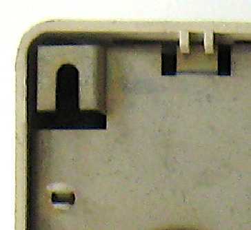
In the photograph you can also see a hole with a bifurcated section of plastic. This is a nylon pillar; one of four, which supported the internal Printed Circuit Board. Previously, the "Post Office" had insisted on using brass pillars, screwed or riveted to the base plate. The use of plastic pillars saved about a pound per unit! This was a huge saving. I told the tool maker to ensure that the holes were punched from the "inside" of the metal sheet, so that the entry edges were rounded. This ensured that the pillars were easy to insert but that the sharper edges on the exit side made them difficult to remove.
However, when production time arrived, we found that the pillars were too brittle. Either they couldn't be inserted or the bifurcated feet snapped off. We contacted the supplier, who sent a Sales Engineer to investigate. He told me, privately, that the pillars had been in storage for too long in a dry place and had lost some moisture. He took the entire batch home and left them tumbling in his wife's washing machine overnight. In the morning he returned them in polythene bags, with instructions to keep them in the bags until required. The sealed bags kept moisture inside and ensured that the plastic remained sufficiently pliable.
What he failed to tell me, and what I failed to realise, was that the plastic would dry out in service. Eventually, after some years, the pillars would snap, leaving the PCBs rattling loose inside the housing!
The flexible hinge presented another problem. I had dreamt up this feature to hold the lid in position when closed and when folded upwards (open). To perform this duty it had to be strong but flexible. After many tests on various plastics, I chose "Delrin", an Acetyl Copolymer with properties similar to those of Nylon 6.
Apart from being strong and flexible, it had a property, which other plastics lacked. It did not squeak on the ABS moulding when the lid was opened or closed. 
The plastics toolmaker informed me that "Delrin" had a shrinkage coefficient of around 10%; much higher than most other plastics. This fact meant that the tool cavity had to be made about 10% larger than the finished product size. It meant that the tool could not be used for any other type of plastic because the resultant part would be too large, since other plastics didn't shrink as much.
I decided to take the risk and the resultant product worked perfectly. It seemed that my gamble had paid off until, years later, I discovered that "Delrin" suffered the same problem as nylon. It dried out and, eventually, it would snap when the lid was opened.
I didn't discover this until more than ten years later, by which time the units were well outside any guarantee and were probably no longer in service.
The slide-switch matrix was also moulded in "Delrin" and it also cracked. It was a much larger moulding and this problem was discovered much sooner. The Post Office came close to cancelling the order but relented because the cracks did not affect the function of the sliders.
Another problem, which became evident after several years, is that the ABS plastic housing yellowed with exposure to sunlight.
I see this type of problem repeated in modern designs of the 21st century. It seems that manufacturers don't publicise information widely enough. Also, companies don't empower older engineers to teach young college graduates this type of information.
While new plastics are developed and improved in certain ways, it's still possible to design something with an inappropriate plastic. You still see computer keyboards and car lamp lenses turning yellow. This is not an accident or "a fact of life"; it's evidence of the wrong type of plastic having been specified at the design stage or of some clever purchasing operative having changed the specification in order to reduce cost.
Another common instance of poor design is in plastic moulded pillars with screws. If a thread-forming screw is used, the pillar will often crack within a year. This problem can be avoided, either by using a special thread-cutting screw or by moulding a threaded insert into the pillar. Beware, however, that the pillar is likely to crack around the insert so an additional reinforcing ring should be fitted over the pillar.
* Footnote RS22 exchange
Hi - On the webpage above it states "and the RS22 six foot rack of which only one was ever made - still in service on the island of Sark, I believe". I think you'll find that is an incorrect statement - British Telecom bought 12 of them where they were known as UXE7's (Unit eXchange Electronic No 7) - They were all 2m high versions up to 250 lines:-
Aultbea 205 lines.
Badachro 92 lines.
Diabaig 20 lines.
Poolewe 139 lines.
Torridon 78 lines.
Boat of Garten 247 lines.
Cairngorm 36 lines.
Carr Bridge 190 lines.
Dulnain Bridge 145 lines.
Nethy Bridge 264 lines.
Kincraig 147 lines.
Laggan 67 lines.
Within a year of their introduction, the digital UXD5A had appeared and BT bought no more RS22s.
The UXE7's had all ceased in service by early 1995 and been replaced by digital systems. All had gone except for Cairngorm where the subs had been moved onto Aviemore and the UXE7 lay abandoned. I recovered Cairngorm in Jan 1995 and still have all the cards, manuals and circuit diagrams in the loft. I was also present a couple of months later when Diabaig UXE7 was changed over, being the last analogue exchange on the mainland in the Highlands.
I recovered the very last public electro-mechanical exchange in mid July 1995 (a small 20 line IAX5 - Island Automatic eXchange No 5). It was still working a month after BT had had their 'Last Electro-Mechanical Exchange' ceremony at Crawford. But the IAX5 was on the UK's most remote inhabited island (Foula) way out in the Atlantic to the west of the Shetland Islands. I also have the oldest working exGPO exchange, a UAX5 which served Long Houghton from 1929 until 1950 and miraculously survived intact until I discovered it in the 1990's.
Hope this helps?
regards
Ian
Send this page address - CLICK HERE - to a friend !
Leiterplatte