| 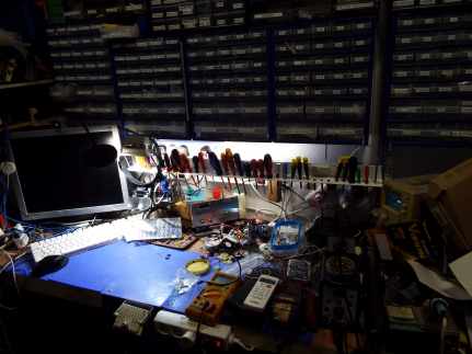
| I made a screwdriver rack in the electronics workshop. I made this from a piece of scrap, white aluminium angle. It's simply suspended on two cable ties so that I can lift it to get at the mains sockets behind it. A bit of bad planning, perhaps, but I don't know where else to put them. Anyway, I no longer have to rummage in an overflowing drawer to find the correct screwdriver. |
| Some months ago I had accidentally short-circuited my variable voltage bench PSU output (again) and it died. I'd already repaired it once but it simply wasn't short-circuit proof. Also, the 24 volt SMPSU died in my wife's microphone "quiz" amplifier and, even though I replaced every semiconductor in it, I couldn't get it to work. I bought a replacement. |
| 
| I decided to assemble another variable-voltage PSU in the now empty housing of the dead 24v PSU, using the same toroidal transformer that has two 18v 0.42A windings. I connected them in parallel to get 18v RMS at 0.8A. |
| I used a different control module that has a current-limiter adjustment. This function and the voltage adjuster were provided by two trimmer potentiometers on the PCB, which wasn't convenient. So I desoldered the trimmers and wired in two panel-mounting potentiometers. |
| 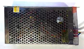
| The module is rated at 10 Amps (5 Amps without a fan). As I'll be drawing less than one Amp, I didn't fit a fan. The housing has plenty of ventilation. |
| 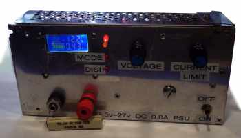
| The front panel is messy but functional. Here I connected a 22 Ohm 11 Watt resistor to the output terminals, increased the voltage to 12 volts then backed off the current limiter until the red LED lit, indicating that the limiter was active. |