Installing a Primo Ceiling Fan with Remote Control | |
|
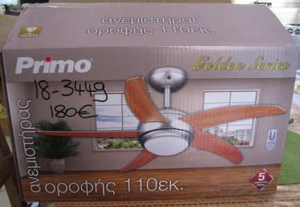
| My wife wanted a ceiling fan in the bedroom so I told her to buy one and I'd fit it. So she spent 180 Euros on the heaviest unit she could find! |
|
| The instructions stated that the ceiling must be capable of supporting 100 kg weight. That was a problem because our roof is made of reinforced concrete a foot thick and insulated inside with 32 mm expanded polystyrene sheet and plasterboard. |
|
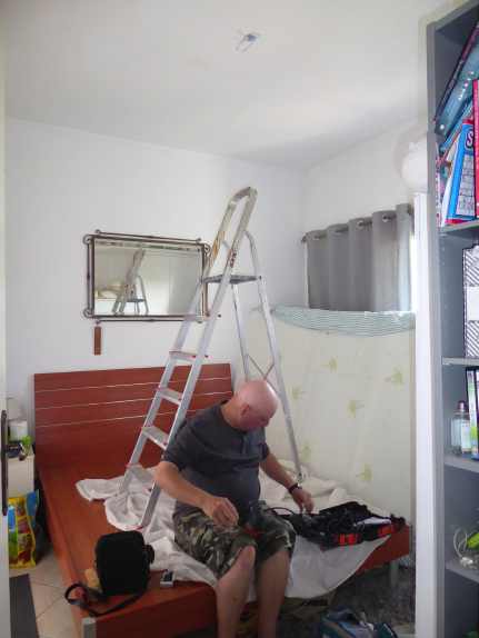
| I removed the mattress and placed the step ladders on the base, which is well supported by the steel frame beneath. Mains power turned OFF. I removed the lamp, which was suspended from a small hook that was screwed into a plastic plug in the concrete ceiling. |
|
| I marked out a rectangle on the ceiling that needed to be cut away. |
|
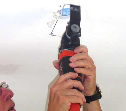
| An electric reciprocating/vibrating tool was used to cut away the plasterboard and blue insulating foam. |
|
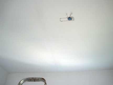
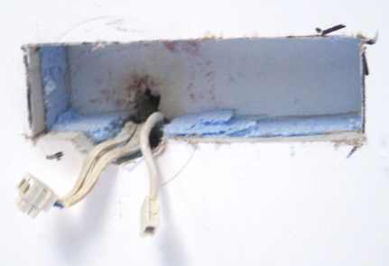
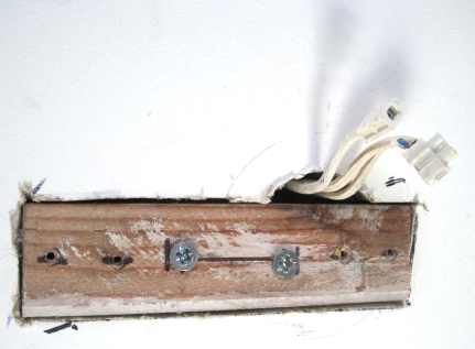
| Closer view of the resultant hole and the existing wiring - live, neutral and earth. Note: I had chosen the position of the rectangular hole so that the short wiring could be connected easily to the screw terminal strip on the support bracket (see below). |
|
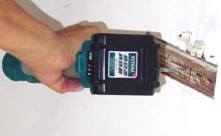
| I cut a piece of wood to fit and drilled two holes through it. With the wood firmly wedged in the hole. I used a drill to mark the hole positions on the concrete ceiling then removed the wood. |
|
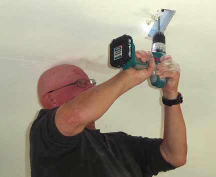
| It was a hot day and it required a lot of effort to balance on the step ladder and drill holes into the concrete. My wife thought that I was about to have a stroke. (The camera lies. I was definitely not as bilious in colour as the picture suggests!) |
|
| With plastic plugs inserted into the holes in the concrete, I tightened two very long screws to hold the wood in place. I had already marked the wood and drilled four pilot holes for the screws that will hold the support bracket. (Two screws were supplied but I added two more, since there were four slotted holes in the bracket.) |
|
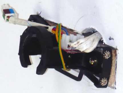
| Support bracket screwed in place. It comes with a 3-way screw terminal strip and a wired plug that connects to the fan assembly. Note the "horseshoe" into which the ball of the fan assembly will be fitted. |
|
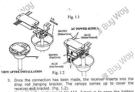
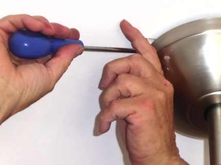
| The remote control receiver unit is separate and I found the instructions confusing. It appeared that the infrared receiver "eye" was meant to be stuck to the ceiling with a self-adhesive pad but there was no slot in the metal cover for the thin cable to exit. However, there was a large, circular hole in the cover that seemed to be suitable for the "eye" to look through but the hole was slightly too small to allow the "eye" to fit. |
|
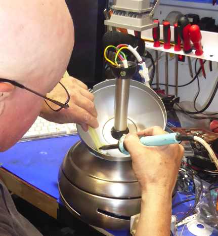
| So I took the unit into my workshop. Rather than attempt to file the hole larger, I held the "eye" against it and used an old soldering iron tip to melt plastic adhesive around the eye to secure it in place. |
|
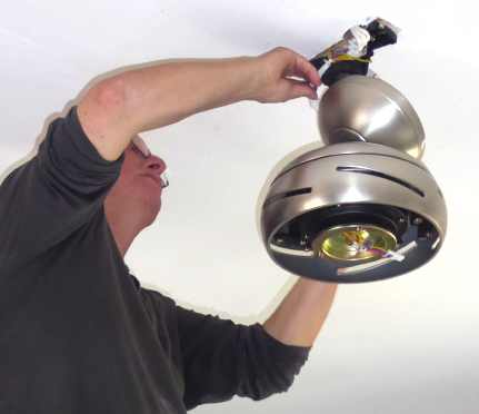
| Now the fan assembly was ready to hang by inserting the ball end into the "horseshoe" of the support bracket. |
|
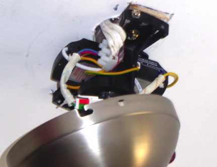
| Here the remote control receiver unit is inserted into the gap provided above the "horseshoe". See the red "eye" protruding slightly from the metal cover, bottom right. |
|
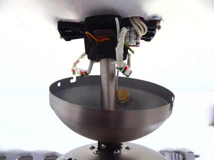
| Cables connected. See the "eye" glued inside. It still has a self-adhesive pad on the rear, with paper disc protector. There was no way to use this adhesive pad. |
|
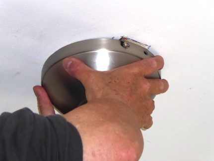
| The cover was pushed up onto two screws on the support bracket and twisted into the slots. |
|
| Two additional screws were inserted into the holes provided and tightened. |
|
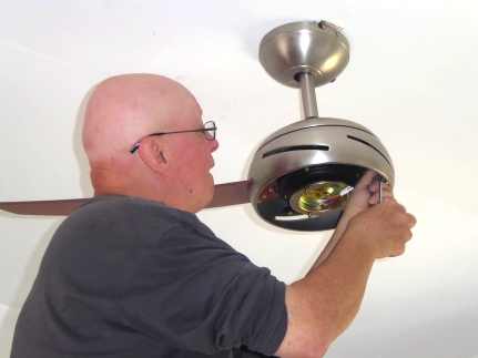
| Now I had to remove the three screws from each blade bracket then reinsert and tighten them with the blade in place. Note to self: I need to expose my head to the sun more often. I'm beginning to look like an ice cream cone. |
|
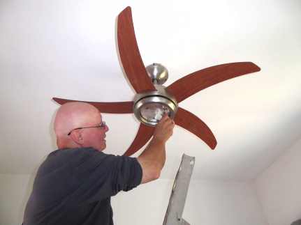
| Five blades fitted and 15 screws tightened. Lamp holder fitted with three screws and connected electrically. |
|
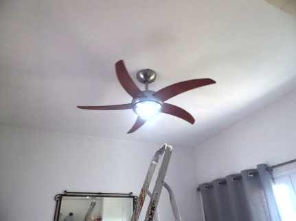
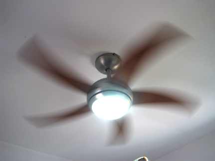
| Bulb fitted and glass bowl screwed into place. Mains power turned on and the remote control works the lamp. |
|
| And the fan works at various speeds selected by the remote control. |
| Send this page address - CLICK HERE - to a friend ! | |