| The "Genie" ESR & Low Ohms Meter designed by Bob Parker 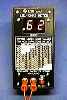 This is a portable microcontroller-based digital instrument for quickly finding those partly-open-circuit electrolytic capacitors in circuit, which cause so many faults in switch mode power supplies, satellite receivers, VCRs, camcorders, TVs, monitors, etc etc! This is a portable microcontroller-based digital instrument for quickly finding those partly-open-circuit electrolytic capacitors in circuit, which cause so many faults in switch mode power supplies, satellite receivers, VCRs, camcorders, TVs, monitors, etc etc!
The kit contains all required hardware and components including banana plugs and alligator clips to make short test leads, but you'll need to provide a 9V alkaline battery and probe-type test leads. SatCure Kit Price £49.95.
Fully built and calibrated £59.95 (includes test probe leads).
Genie-Plus version includes an audible bleep to indicate less than 0.99 Ohm, a softer bleep for 1.0 - 9.9 Ohms and no bleep above 10 Ohms. It has a High brightness LED display and test probe leads £67.45 NLA
*Note: If you are not in the UK or Europe, you can order your kit directly from Dick Smith Electronics in Australia. READ AN INDEPENDENT REVIEW Brief Specifications Measurement range: 0.01 to 99 ohms, auto-ranging
Peak voltage across capacitor under test @ full scale: 100mV
Update speed: 4 readings/second
Power supply: Internal 9V alkaline battery or external 9V DC
Controls: Single push button for power on/off and zero
Dimensions: 2.7 x 5.2 x 2.2 inches (69 x 132 x 56mm) Features * Tests electrolytics in circuit, & test leads are non-polarized.
* Test lead resistance compensation.
* Automatic power off when reading is unchanged for 2 minutes.
* Low battery voltage warning ('b' flashes on right-hand digit).
* Big, easy to read 0.5 inch (13mm) LED displays.
* Table of typical good capacitor ESRs on the front panel.
So your just-built ESR meter doesn't work properly!!With a bit of luck you'll find the reason for your problem on this page... and by the way, the microcontroller (IC2) is almost certainly not defective!
First the basics (by Bob Parker) Soldering and PCB faults...
I've repaired over 20 ESR meter boards (in person and by remote diagnosis) for people who've had trouble getting them to work correctly, and in more than 95% of them the fault has been due to soldering problems. This is such a common problem that in future I'll be charging $$$ for getting meter boards working when the fault is caused by defective soldering. The tinned copper tracks on the PCB are very closely spaced in many places, and a common problem has been tiny 'whiskers' of solder bridging the tracks, especially where they pass component solder pads, in particular around Q3, Q4 and Q5 (all BC328) on the left-hand side of the board. Sometimes these whiskers are completely invisible. Scrape between tracks with a sharp point. Because the component leads and the PCB pattern are all the same shiny silver colour, sometimes people overlook an unsoldered joint. And of course the traditional cold solder joints can happen! The small solder pads are easily lifted by excessive force on components, and I've seen a fine break in a PCB track due to a manufacturing defect (once). The way to identify these kinds of problems is to hold the component side of the PCB up to a bright light, then carefully study the copper side of the board. If necessary, use a magnifier and refer to the PCB artwork supplied with the kit. Some solder bridges look a lot like part of the PCB pattern!
Misplaced components...
It's easy for your mind to wander when you're performing a boring task like inserting components onto a PCB (I know all about that!), and this can lead to components winding up in the wrong place, or the wrong way around. Resistors
One of the most common problems is misreading the colour code on resistors!! Under artificial light, especially the fluorescent kind, many resistor colour bands can appear to be a different colour from what they really are, especially in the case of those awful blue-bodied 1% metal film resistors. Also, I'm told that about 10% of males have some degree of colour blindness which can also cause problems. Please check the resistor placement under natural light (and ask your wife/girlfriend/daughter etc to double check!) if you have any doubts. Diodes
Please make sure that the correct type diodes are in their correct positions, and the right way around. The 1N914 / 1N4148 diodes are tiny little glass ones, while the 1N4004 type are the larger black-bodied kind, with much thicker leads. Transistors
There are four different transistor types in the meter, and it's easy to mix them up. Also it's possible to insert their leads into the wrong holes- check to make sure the flat part of the transistors is facing in the right direction.
Specific faults, and what to check...Abnormal Display 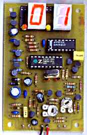 Right-hand display shows weird character (and right-hand decimal point LED might be on), but only while button is pushed: The microcontroller is probably not running... check around XTAL1 and C11 / C12 (both 27pF). Right-hand display shows weird character (and right-hand decimal point LED might be on), but only while button is pushed: The microcontroller is probably not running... check around XTAL1 and C11 / C12 (both 27pF).
Both displays are working, but show weird characters: Almost certainly a short between PCB tracks, probably around the pins on the 28 pin IC socket holding the displays, or around IC3 (4094). Some or all segments of one display don't light: Try swapping the two displays... if the fault moves too, you have a faulty display. You can probably test the unit with another common-cathode 0.5 inch display such as an NTE3079, though it will probably be quite dim. Replacement high brightness displays are available from SatCure. Order them in pairs so they match. Some incorrect segments light dimly on the right-hand display: Q12 (BC338) might be low in gain, or R28 (4.7k) is the wrong value. Right hand display shows '8' then '-' at switch-on, and left-hand display never lights: Q12 (BC338) or one of its connections is probably open circuit. Display dim: Q1 (BC328) low gain or faulty.
In extreme cases this can cause additional symptoms:
Display dim. Display won't stay on when ON button is released.
If display works correctly (EA followed by "-") then it may switch off when a measurement is attempted.
Power Control Problems Meter won't stay switched on after releasing the button: The fault is in the area of Q2 (BC338). Check for solder bridges, bad joints, wrong orientation of Q2, and that R3 = 15k and R29 = 2.7k. Also try replacing Q1 (BC328). Meter switches off instead of zeroing: It will do this if the test lead circuit resistance is higher than 0.99 ohms. Check that the nuts on the banana sockets are tight, and that the banana sockets and plugs aren't oxidized. A solid squirt of CRC Contact Cleaner on the plugs then some serious jiggling in their sockets can help a lot. Meter is permanently on, and displays '??' after the button is pushed: Check for solder bridges in the area of Q1 (BC328), Q2 (BC338), R1 (10k) and R2 (4.7k). Also check that Q1 and Q2 are the correct types. At switch-on, meter permanently displays 'EA' and cannot be switched off, and shorting the test leads has no effect: There's probably a problem around Q9, Q10 (both BC558), Q11 (BC338), R19, R20, R21 (all 10k), R22 (470k), or C10 (0.47uF). Possibly a solder bridge in the area, or a wrong-type transistor in Q9, Q10 or Q11 position. Press ON and EA is displayed followed by 00 and left LED. These remain ON permanently or entire display and LED may go OFF permanently. Single "standby" segment never appears:
Possible Cause: R27 4k7 not connecting 5v to Q12 collector/Q13 base (broken track) or faulty Q12/Q13. Nothing lights up when ON button is pressed:
Possible Cause: R4 47k (next to Zilog micro notch end) and R2 4k7 (next to 10k pot) transposed.
Incorrect Readings Meter will read some resistors correctly, but gives absurd readings on others: This is a common fault! Carefully check the values of R6 (10k 1%), R8 (1k 1%) and R10 (100 ohm 1%). Dick Smith Electronics are supplying an 82 ohm 1% and a 5.6 ohm 1% resistor in the kits to help with calibration.... the 82 ohm 1% looks very much like a 1k 1% under artificial light, and a lot of constructors have accidentally installed the 82 ohm 1% resistor as R8. If that's not the problem, check for solder bridges in the area of Q3, Q4 and Q5 (all BC328), where the PCB tracks are very closely spaced (and where a lot of constructors have made solder bridges). Meter permanently reads '.00' and won't switch off: First make sure you installed the banana sockets with their insulating rings between the mounting nuts and the front panel... otherwise the test leads will be shorted to the metal front panel! If that's not the problem, there's probably something wrong in the pulse amplifier circuit consisting of Q7 (BC548) and Q8 (BC558) and their surrounding components. Check that Q7 and Q8 are the correct types and the right way around, and that D5 and D6 (both 1N914 / 1N4148) are the right way around. Also check carefully for solder bridges and bad joints. You should measure about +0.6V on pin 8 of IC2 (Z86E0408 / Z86E0412); if you don't, then there is definitely a fault in this part of the circuit. Meter shows 'EA' until shorting and separating the test leads, then freezes on a very low reading: Look for an open circuit or solder whisker around R5 (2.2k), R6 (10k 1%) and Q3 (BC328). The meter board where I saw this fault had a detached solder pad on R5.
Getting technical...Here are some important waveforms taken from a correctly-working meter
with a x10 (10 megohm impedance) probe and the test leads open-circuited.
| 
| IC2 pin 10 This is the reference voltage waveform, critical to measuring ESR/resistance and battery voltage. It's a slow signal which must be measured with a 10 megohm probe, and will tend to look like a jumping dot on an analog 'scope. If it's different to this, look for a fault around Q9, Q10 (both BC558), Q11 (BC338), and their surrounding components. | | 
| IC2 pin 8 This is the output voltage from the pulse amplifier, and should be seen as several bursts of pulses per second. It's important that its 'base' voltage is close to +0.6V, and the peak voltage is close to +5V as shown here. If it's different to this, look for a fault around Q7 (BC548) and Q8 (BC558) and their surrounding components. | | 
| Waveform on test leads This is the voltage you should see on the open-circuited test leads, occuring as several bursts per second. If the peak voltage is much different from the +500mV as shown here, look for a problem in the area of D3, D4 (both 1N4002 or similar), Q3 (BC328) etc. | | 
| IC2 pin 15 If the meter's operating more or less correctly, the microcontroller will go to the top (10 to 99 ohm) range and be driving Q3 (BC328) with this waveform. If it's absent but you see this signal on either pin 16 or 17 instead, then it probably indicates a fault (such as a wrong resistor or solder bridge) around Q3 or Q4 (both BC328). |
Found a faulty transistor?? It's possible your testing has revealed a defective transistor in your kit; it's rare but it has happened. If you live in the UK or Europe, you shouldn't have any trouble finding a replacement.... SatCure stocks them. But if you're in North America you'll find them hard to get. Mouser Electronics sells them cheaply (thanks to TVSteve for this information), otherwise they can be replaced by types readily available in the US: The common 2N3904 will replace the BC338 and BC548, and the 2N3906 will replace the BC328 and BC558.... but note that the 'flat' on the 2N3904/6 will face in the opposite direction to the 'flat' on the 'BCxxx' it's replacing!!
Phew!! I hope this page has enabled you to find and correct the problem(s) in your ESR meter, and that it's working OK now.
Hints for techs using the ESR meter! Here's the current list of hints. If you have any handy suggestions I can put on this page, please E-MAIL ME! (1) The way to hold the 9V alkaline battery in place is to lay it in the bottom of the case and place a suitable-sized piece of thick foam plastic over it. Then the circuit board will hold it snugly in place when the front panel is screwed down. (2) The "Approximate worst ESR values" table on the front of the meter were taken from a fairly old capacitor catalog, and capacitor technology has evolved a bit since then. Many 105 degree C electrolytics have an ESR up to nearly double those values even when brand new, and other electrolytics have a lower ESR even when old. From my experience if an electrolytic has an ESR more than double the table value for its capacitance and voltage rating, it's wise to check it against a new one and/or replace it to remove the chance of it causing problems in the future. Hank Sievers said, "Bob Parker's meter can also be used as a go-no go type. I have found that I can consider everything below 3 ohms as good, and all over 10 as bad, with very few falling in the doubtful category". I agree that except for very large and very small caps, this is a useful 'rule of thumb'. Thanks, Hank! (Note from Martin: The "Ultra-Low" ESR capacitors used on the output side of many switch mode PSUs need to be LESS than 0.1 Ohm so bear that in mind. These are often coloured brown with a gold stripe). (3) The 'DISCHARGE CAPACITOR BEFORE MEASURING!' warning on the meter front panel is a little over-cautious.... 'Test only discharged capacitors!' would have been better. Nearly all electrolytics are discharged by their surrounding circuitry within a few seconds of the power being disconnected, so you can generally poke around with the meter without worrying about this. The only caps which are likely to need deliberate discharging are the main filters in amplifiers and other large power supplies. (4) Glenn Watkins [http://www.comcat.com/~blueribb/index.htm] has pointed out that a shorted or partially shorted cap can check OK (ie: low resistance), so if you check a cap and the indicated ESR seems too good = low to be true, it's wise to check it out with an ohm meter. (5) The meter puts out regular bursts of 10us pulses at a 2KHz rate, at an open-circuit amplitude of about 600mV P-P. At a pinch you can use it as an audio signal source to check speakers, amplifiers etc. The pulses have a fast rise/fall time, so it would probably make a crude RF signal injector as well. Thanks to 'Kiwi' Joe Lussy for suggesting this! (6) Glenn Watkins also said, "It's very hard to press the test lead tips together to get a steady reading before pressing the button to zero the display. I found that if the test leads have sharp tips, you can press them both on a solder pad (on a PC board) and the leads will penetrate the solder a little giving a good solid reading". Thanks Glenn! (7) Varying contact resistance between the banana plugs and sockets can cause unsteady readings, but if you give each plug a big squirt of CRC "CO Contact Cleaner" then rapidly jiggle it in its socket for a few seconds, this reduces the problem considerably. Also be aware that the nuts holding the banana sockets can work themselves loose over time, causing a variable and gradually increasing indicated test lead resistance... this happened on my own prototype meter and others I've heard about. (8) If you'd like to get more battery life out the meter (and are feeling a bit adventurous), you can replace IC1 (78L05) with an LP2950CZ-5.0 and replace R26 (10k) with a 27k. Then adjust VR1 so the low battery warning triggers at 5.6V instead of the original 7.0V. Thanks to G. Freeman in South Australia for this idea which was published in the August '98 issue of Electronics Australia magazine.
If you own another ESR meter such as Doug Jones' highly respected Capacitor Wizard and would like a chart of approximate worst-case ESR figures like on my meter for reference, CLICK HERE to download one as a text file you can print out! Thanks to M Davis for suggesting that I make this available!
And now the answer to the question 'everyone' is asking... Why does the meter flash 'EA' at switch-on? Answer: 'EA' stands for 'Electronics Australia', the name of the illustrious old magazine this meter appeared in as a construction project, back in January 1996.
Finally a big 'THANK YOU' to all you techs who've bought this meter kit and said good things about (and constructively criticised) it, both on the sci.electronics.repair newsgroup and to me directly. I really appreciate it! Bob Parker. Visit my Home Page and see my other kit designs!  Bob Parker Bob Parker |