|
| |
Electronic Doorbell Driver | |
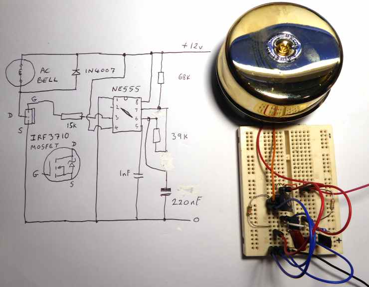
| I bought a doorbell that required a 12 volt AC transformer. However, I have a 12 volt DC supply from my solar-charged battery system, which is always there - even during a power cut. I wanted to use this. So I designed a simple square-wave AC generator using an NE555 I.C. and used that to turn a power MOSFET rapidly on and off. With this connected to the doorbell solenoid, I adjusted the frequency to give the best ringing sound. Here's the circuit diagram and the breadboard lash-up for testing:
| |
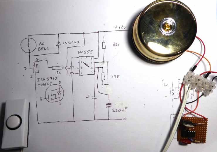
| Here are the same components transferred to a copper stripboard.
Notes My doorbell had an internal diode connected in series with the solenoid coil so it works with my circuit only when it is connected the right way round. (It's OK to experiment. No harm will occur if it's connected in reverse.) The IRF3710 transistor and the NE555 I.C. are drawn in the diagram as viewed from above - NOT looking at the connections. Resistors can be 0.125 Watt or greater. The 220nF capacitor is rated at 16 volts or greater and its value determines the ringing frequency. I used a polyester capacitor but the type is not critical. The 1nF capacitor is rated at 16 volts or greater. I used a ceramic disc capacitor but the type is not critical. The value of the 15k resistor is not critical. The values of the other resistors are not critical but they WILL affect the ringing frequency. The DC supply may be as high as 15.0 volts and the bell will probably work from only 9 volts, if required. | |
| Send this page address - CLICK HERE - to a friend ! | |