Mac G3 G4 PowerBook iBook Charger Repair Power Supply A1021 A1005 | ||
|
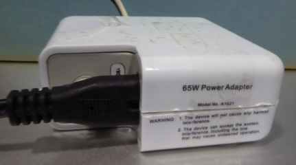
| My A1021 charger died. I pried apart the two shells to look inside. Although this charger had "Apple" printed on the circuit board, I don't think it was genuine. | |
|
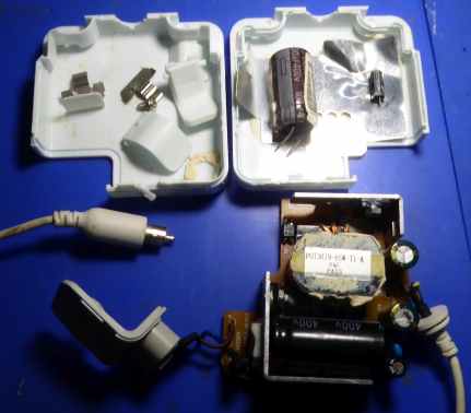
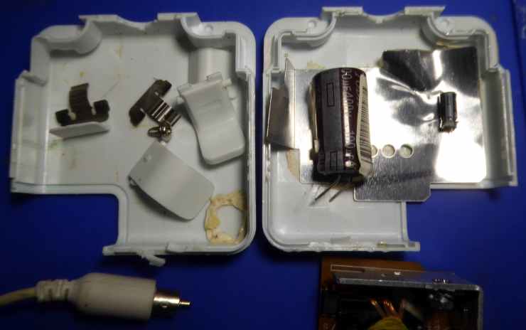
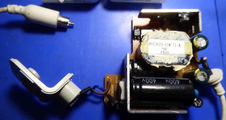
| The two wire-binding hooks each comprise a metal spring clip and two plastic mouldings. Take careful note of how these fit together. The metal goes in first, followed by the smaller moulding then the larger moulding. See larger photo, below. There's also an aluminium foil shield. Silicone rubber adhesive prevents the parts from rattling and this needs to be cut away with a thin chisel or sharpened flat-blade screwdriver. | |
|
| ||
|
| The fuse measured short-circuit (correct) so it seemed that the fault had not done serious damage. The large electrolytic capacitor had a very slight bulge at the end. This is not easy to see in the photo. It should be perfectly flat but it's very slightly domed, indicating internal pressure (failure mode). | |
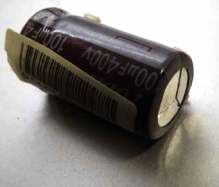
| I replaced it with the one that you see below, ensuring that the wires were insulated and it was the correct way round. | ||
|
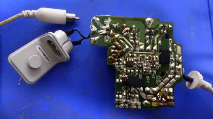
Below is the underside view of the Printed Circuit Board. | ||
|
| ||
| I connected mains power (DANGER!) and the output voltage measured 24.8 volts DC. I reassembled it and glued the plastic shells together. | ||
|
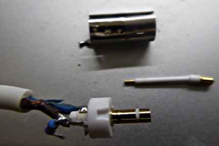
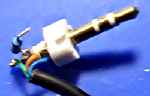
| I had another, identical charger unit where someone had tripped over the 24v cable, pulling the centre pin out of the plug. I cut away the moulded plug to look inside. The pin is not connected to anything! It is not required. There's a 120k resistor* connected between the 0v wire and the outer metal cylinder. (I removed the cylinder for clarity). | |
| I don't know the function of the 120k resistor or the metal cylinder. | ||
|
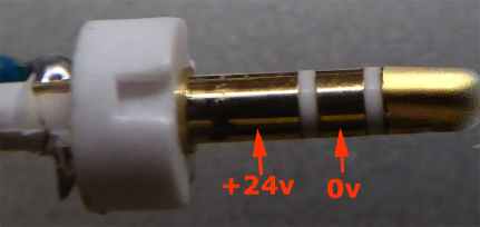
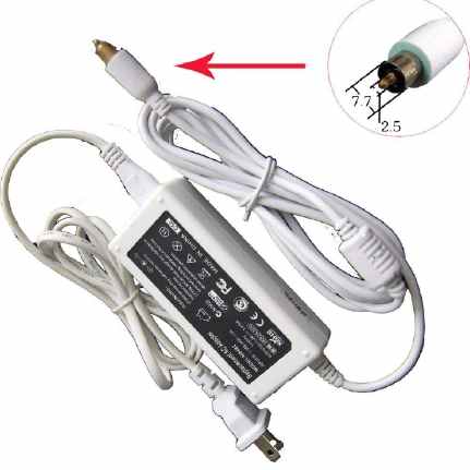
| When the plug is inserted into the Mac computer, the tip of the plug gets +20v from the computer. This indicates charging mode (and an LED + 10k resistor could be connected between tip and 0v to indicate charging). When charging is complete, the tip is "floating". | |
| Earlier, genuine, Apple chargers use this tip connection to indicate charging (amber LED) and charged (green LED) but I haven't figured out how they light the green LED. It seems to me that a schmitt trigger transistor circuit would be required in the plug. Note: some chargers use twin flex for the DC lead and some use coaxial cable. If you can find a suitable 7.7mm diameter metal cylinder (maybe from an RCA "phono" plug, it might be possible to combine it with a 2.5mm stereo jack plug and connect it to a standard 24v DC power supply to use instead of the proprietary one which, one day, will no longer be available. | ||
|
| Here's an aftermarket charger for G3 and G4 Mac laptops that is currently available via Amaz0n. | |
|
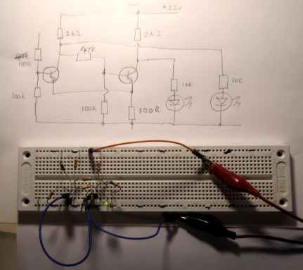
| To try to simulate the original Apple plug, which lights up amber while charging and green when charging is complete, I drew up a Schmitt trigger circuit and built a breadboard prototype. | |
|
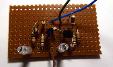
| Having confirmed that the circuit worked, I transferred it to copper-clad perforated stripboard. This is too large to fit inside a plug so it would have to be put in a separate housing and connected in line with the DC plug. | |
|
| I used 2N3904 NPN transistors but any general purpose silicon NPN transistor will do. The common emitter resistor is 100 Ohms. | |
|
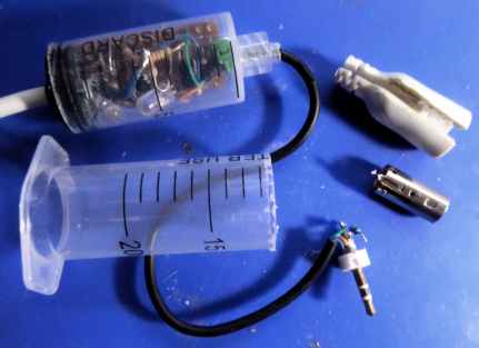
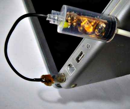
| I cut the end off a syringe to house the PCB assembly and used a short length of thin USB cable (4-core) to connect the plug. Now I have to either find a way to glue the original semi-flexible moulding onto the plug or fashion a new cover out of "Sugru" silicone putty.
| |
|
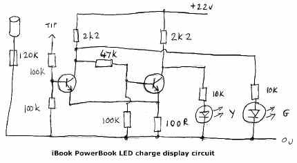
| The 120K resistor in the plug didn't seem to serve any useful purpose so I think it's only there to provide a leakage path to ground. I moved it to the PCB and used the 4th wire in the (originally unscreened USB) cable to connect it to the plug's metal cylinder (see circuit, above). | |
| I cut a piece from another, smaller syringe to form the plug body and glued it to the metal cylinder with hot melt ashesive. I fitted a cable tie tightly to the (black) USB lead and melted hot glue into the new syringe "plug" to act as a cable restraint. I applied too much heat with an old soldering iron tip, which turned the glue brown. The end result is a bodge but it works and it was an interesting experiment. Is it practical? I don't think so. If someone trips on the cable again, it's going to snap or rip out from the plug or LED indicator. | ||
| Send this page address - CLICK HERE - to a friend ! | ||