| | Mono Callmaker
P. A. BURTON (about 1975)
UDC 621.395.636:616-7
This article describes the latest addition to the British Post Office range of repertory diallers: the mono Callmaker. This has a particular application for customers with physical disabilities as well as appealing to a commercial market.
Note: For the field trial, the Mono Callmaker will be known as the Single Number Callmaker
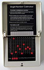 
FIG. 1-Mono Callmaker (Autodial No. 401A), shown with lid open and closed
INTRODUCTION
The British Post Office has for many years provided the Sender No. I to assist handicapped telephone subscribers call a public-exchange operator simply by lilting the handset and pressing a button. The sender coasists of a notched dtsc that is rotated by a 9 V batteryoperated motor. Pulsing contacts are positioned such that they give one break pulse to line per notch, and off-normal springs duplicate the function of those of the conventional dial. The pulsing and (off-normal spring-sets are based on those designed for the now obsolete Dial, Automatic No. 10, supplies of which are rapidly diminishing.
The Mono Callmaker has been developed as a line-powered electronic replacement for the Sender No. I, and as an addition to the range of repertory diallers currently available. It provides more facilities than its predecessor in that, although it can send still only one number, that number can be chosen and programmed by the customer; the device is not limited to sending the operators' code. The callmaker is thus capable of satisfying more commercial applications. The title of the device is the Autodial No. 401A but, for marketing purposes, it is known as the Mono Callmaker. (Field-trial items will bear the title "Single Number Callmaker".)
FACILITIES
One telephone number of up to II digits can be selected using a matrix of slide switches (see Fig. 1) to set the required digits. Three additional switches beneath the number-setting matrix enable a long inter-digital pause (IDP) to be inserted, if required, after each of the first 3 digits. A long IDP is needed when the callmaker is fitted to a PABX extension and access is required to exchange lines or inter-PBX circuits. The length of the IDP can be set to either approximately 2s or 5s by shifting a strap.
Originally, the device was intended to be wawl-mounted only. This was because of the problem of re-orienting a mercury-wetted pulsing reed-relay if the callmaker were, as an alternative, to he used horizontally on a table. However,
in the final design, a solid-state pulsing element is used, and it is therefore possible to operate the callmaker in any plane.
The callmaker is operated by a single remote change-over switch. This is normally fitted in the associated telephone but, for the more severely handicapped subscribers, an actuating switch appropriate to the particular user's needs can be installed.
PHYSICAL DESIGN
The case has been designed to accord with the modular dimensions recommended for new customer apparatus, and is 250 x 150 x 50 mm in size. The external appearance has been deliberately kept plain and simple to allow the unit to merge into the normal living-room background. The design incorporates 2 novel double-acting hinges that allow the lid to rotate through 180°, hold it open for the number to be set, and give a completely plain surface when the lid is closed (see Fig. 1).
All the electrical components, and the number-setting matrix, are mounted on a single printed-circuit board which extends the complete length of the unit and is supported on a pressed-metal base using snap-in plastic pegs. The sliding contacts of the number-setting matrix are mounted in a plastic moulding having a specially designed profile that provides guides for the setting switches and a means of ensuring their precise location when set. The fixed contacts consist of gold-plated wires soldered to the printcd-circuit board. An anodizedaluminium label, bearing the markings for the number-setting matrix and the Post 0ffice Telecommunications" motif, is used as a face plate for the matrix. A second anodizedaluminium label inside the lid presents the complete operating instructions, and also includes an area on which to write the selected telephone number.
The complete case and lid, which are fastened to the base by a single screw, are removable, giving access to the connexion terminals and the long-IDP strap. Press-out sections in the case cater for connexion by cable or standard telephone cord. The base has rubber feet for table-top use, and keyhole slots for wall-mounting. The components on the part of the printed-circuit board that is exposed when the cover is removed are protected by a shroud which prevents damage during installation.
The metal base has holes that coincide with the press-out sections in the case, and a clamp to retain a connexion cord. The rubber feet are recessed to give a low profile, and do not need to be removed when the callmaker is wall-mounted. The case fits over 2 tongues at the top edge of the base, and is secured by a single screw in a tapped extentsion to the cord clamp.
CIRCUIT OPERATION
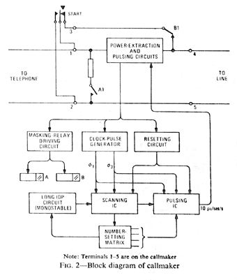
Fig. 2 shows a block diagram of the callmaker connected to a telephone circuit. When the callmaker is not in use, the line is connected through to the instrument via masking-relay contact Bl and the break contact of the start button. To activate the callmaker, the start button is pressed to remove the short-circuit from the power-extraction circuit. Power is drawn from the line to start the clock-pulse generator, operate the 2 masking reed-relays, and apply a reset condition to the scanning and pulsing integrated circuits (ICs). Contact B1 maintains the power supply to the callmaker when the START button is released, until pulsing is completed. Contact A1 provides a low-resistance pulsing loop, guarding the telephone against acoustic shock.
The clock-pulse generator supplies 2 clock-pulse streams, f1 and f3, to the 2 p-channel metal-oxide-silicon ICs: the scanning IC and the pulsing IC. Two further streams, f2 and f4, are derived and used internally by the ICs from f1 and f3. Streams f1 and f2 supply power to the ICs; f2 and f4 are used only to control gales. The scanning IC interrogates the matrix of programming switches sequentially and converts each digit of the telephone number into a 4 bit binary code. The code for each digit is passed to the pulsing IC, where it is stored and processed in a way similar to that previously described for loop-disconnect-signalling pushbutton telephones. The 10 pulses/second output is used to drive a pair of high-voltage transistors that constitute the solid-state loop-disconnect pulsing element. At the end of pulsing, the reset condition is again applied to the ICs to prevent misoperation when the masking relays are released and the power supply removed.
When a long IDP has been programmed, the scanning IC interrogates the matrix and forwards the information as described above until it reaches the programmed pause. It is then inhibited from further interrogation by the long-IDP monostable circuit. When the monostable circuit resets, interrogation continues.
CONCLUSION
Prototypes of the Mono Callmaker have undergone extensive laboratory testing, and the next stage is to obtain small-scale production and field-trial experience. Although primarily intended as a dialling aid for handicapped customers, the callmaker could well find applications in other fields.
ACKNOWLEDGEMENTS
The author wishes to acknowledge the help given by his colleagues in the Telecommunications Development Department, and by GEC Telecommunications Ltd., who carried out the development work.
References
1 Simmons, T. G.. and BURTON, P. A. Repertory Diallers. POEEJ, Vol. 62, p. 188, Oct. 1969.
2 Card, S. E., and L ittlemore, D. T. Push-Button Telephones. POEEJ, Vol. 67, p. 224, Jan. 1975.
More... and more... | |