|
| ||
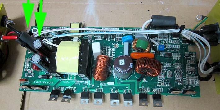
PowerBright Inverter Fault Smoking Capacitor FailureThe green arrows indicate the capacitors that I replaced to cure the fault. You'll need a CP4750HTT 47uF/50V and two CP220025HTT 2200uF/25V from click HERE
| ||
| I bought the "Power Bright APS300-12 Pure Sine Power Inverter 300 Watt 12 Volt DC To 110 Volt AC " on 15th July 2010 from Amazon.com It arrived a few weeks later and wasn't put into service until the beginning of October 2010. I needed it to run my office computer system during periods of power outage. I mounted it in a plastic box in a shady area outside the office, with two 6V 200AH batteries and two battery chargers (also from Amazon). A fan was installed to draw warm air out of the box.
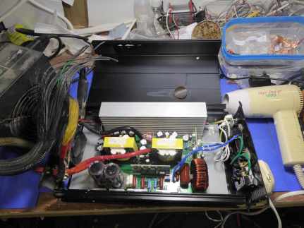
On October 4, 2011 my computers died. I checked outside and smoke was pouring from the inverter. The LED was flickering red/green alternately. I switched it off and disconnected it. To dismantle it you must remove the four black screws at each end then lift out the L-section yellow metal cover. Remove the silver screws in the black heatsink and the little steel brackets inside, which clamp the transistors to the grey heat-conductive silicone insulator sheet. Remove the 5 silver screws holding the PCB (printed circuit board) to the base. To remove the faulty capacitors, you'll need a VERY hot tip soldering iron (at least 400 °C) and desoldering braid such as "solder wick". Click HERE for soldering instructions.
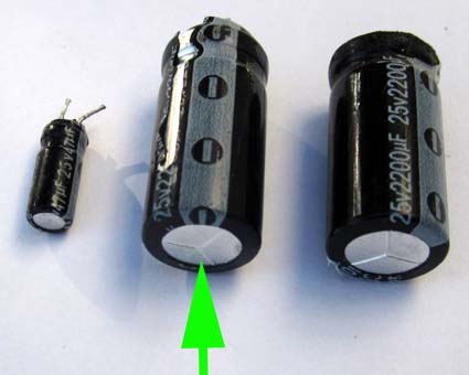
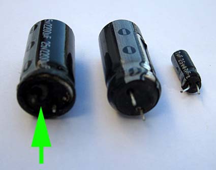
I could see that the top of one of the capacitors was bulging slightly - a sure sign of internal pressure, indicating total failure. When I turned the PCB upside down I could see a hole burnt around one of the capacitor leads, indicated by the arrow in the photo below.
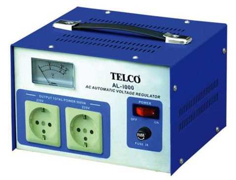
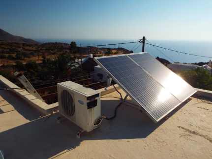
I cut away the carbonised portion of the PCB. Luckily, it didn't need repair because the copper land was still intact and there was enough strength around it. If it had needed repair, I would have used epoxy resin with glass fibres, and solder braid to reinforce the copper land. Conclusion: in my opinion, the original capacitors were unfit for purpose and early failure was inevitable. (In my case they lasted for exactly 12 months.) The capacitors that I used to replace them have a very low ESR (effective series resistance) and should last for several more years. I think I was very lucky to have been present at the time of failure, otherwise the inverter might have been damaged beyond repair. My advice to anyone owning one is to replace these capacitors BEFORE they fail. You'll need a CP4750HTT 47uF/50V and two CP220025HTT 2200uF/25V from click HERE 2013 The inverter is still working fine with the replacement capacitors but I replaced it with a more reliable model. In July 2013 I added two 235Wp solar panels and a Phocos MPPT 100/30 MPPT charge controller. (I'm guessing that this accepts an input of up to 100 vDC and outputs up to 30A.) Mains power now enters via a TELCO AL-1000 Automatic Voltage Regulator that gives some protection against voltage fluctuations and spikes.
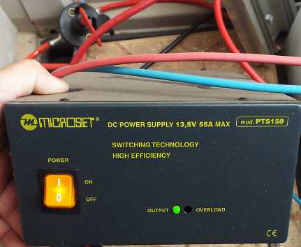
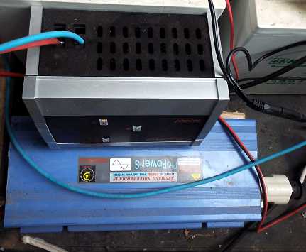
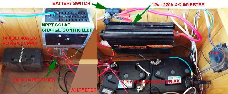
The TELCO feeds a MICROSET PTS150 30 Amp power supply, adjusted to give 14 volts. This is passed through a car battery cutout switch in case of problems (top left in photo below) then through a 40HF10 40 Amp rectifier on a heatsink (top right in photo below), which drops the voltage to 13 volts, and then into the batteries.
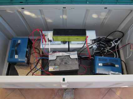
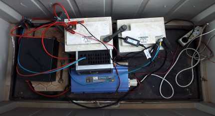
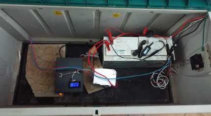
The "UPS" box holding mains power supply unit, rectifier on heatsink, two 6v 200AH deep-cycle batteries, solar panel power controller and 600W Sterling Power Inverter. The solar power controller feeds the required voltage into the batteries when the sun shines.
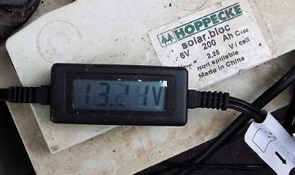
Digital voltmeter shows battery voltage.
Why use these really expensive "deep-cycle" batteries? Well, if I used one or two car batteries, they wouldn't last as long. They aren't designed for this type of charge-discharge work. Of course, if you have an unlimited supply of car batteries and you don't mind replacing them every 6 months, try it!
Power controller (fed by the photovoltaic panels) sitting on the 600W Sterling Power Inverter that is fed by the batteries to provide mains power to my computers.
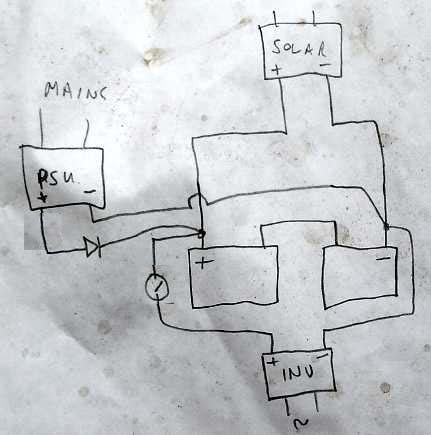
One day I'll be able to afford to have a proper cabinet! The wiring sketch. The 14 volt, 40 Amp Power Supply Unit (+) is connected through the 40 amp rectifier (on an aluminium heatsink) then puts 13 volts into the batteries. The battery is connected to the heavy-duty car battery cutout switch (for safety) to the inverter. When the sun shines the photovoltaic panels feed up to 60 volts into the Charge Controller. This puts more than 13 volts into the batteries so NO current is taken from the Power Supply Unit during this time. When the sun goes down, the Power Supply takes over again. Simple!
Initially I tried to use a relay to switch between solar power and Power Supply automatically but the relay contacts ran hot and I found that the rectifier did a better job without the need for moving parts. It drops about a volt so the 40 Amp DC power supply output was increased to 14v to compensate. On a sunny day, the solar panel(s) with MPPT charge controller provide free energy (apart from the initial cost). But note that this system works without solar input if required. | ||
|
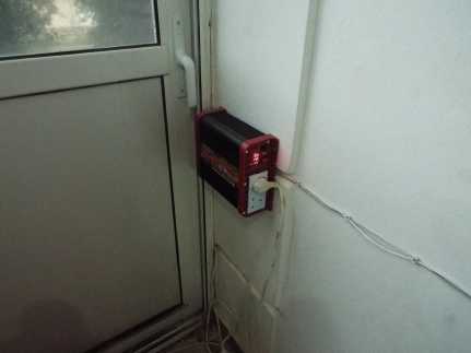
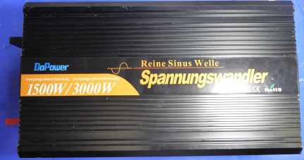
November 8, 2014 UPDATEThat Sterling inverter died October 25, 2014. My own fault for "installing" it in the plastic chest outdoors. In winter it becomes damp. So I've replaced it with a Sterling Power Pro Power SB 600W Pure Sine Wave Inverter via eBay. This time, I've mounted it on the wall in my office. The cables were just long enough to reach the chest outside.
The outdoor chest is looking a little tidier but I need to do something about the solar voltage converter, which is beginning to corrode.
The new inverter is MUCH more efficient. The battery voltage is consistently higher (lower drain on it) and the inverter's fan comes on only rarely and for just a few seconds at a time.
June 22, 2017 UPDATEThat Sterling inverter died without warning on 12 June 2017, having lasted 2 years and 7 months. The power output went off and the red LED warning light came on. I looked inside but nothing has obviously failed. I have ordered a replacement. Clearly these "cheap" inverters are not designed to last a long time in continual use. The Replacement
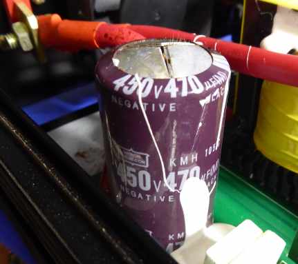
July 13, 2018 The replacement inverter just expired. The smoke came out.
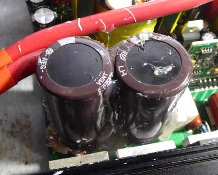
I replaced this failed 470uF capacitor with two 220uF capacitors (all that I had available at the time). I bodged them in place with copious amounts of hot-melt adhesive.
| ||
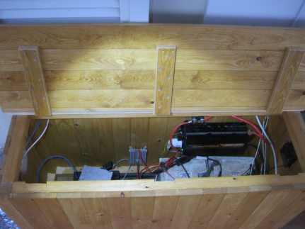
| November 28, 2021 The repaired DoPower inverter is still working! I have replaced the plastic chest with a wooden chest that is now under cover.
September 24, 2022 The repaired DoPower inverter is still working but I must replace the AGM batteries, which have passed their useful life. | ||
| October 5, 2022 I replaced the 12-year-old batteries and tidied up the contents of the box.
| ||
|
| The wiring remains the same. | |
| Send this page address - CLICK HERE - to a friend ! | ||