|
| ||||||||||||||||
| The following article is taken from HOBBIES magazine issue 607 dated March 11th, 1933. Despite the date, the basic principles still apply today.
| ||||||||||||||||
|
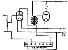
| The normal and, indeed, the only way in which grid bias was applied up to about two years ago (and that still used by the majority of listeners) is to connect a small dry battery in the grid circuit of the amplifying valve in such a way that the positive terminal is joined to the filament or cathode wiring, and the grid of the valve is connected to one of the negative battery tappings. This has the effect of rendering the grid negative with respect to the cathode or filament by a value equal to the voltage of that part of the battery tapped into the circuit, and the scheme is shown in Fig. 1. |
Advantages of Auto Bias.
There is, however, a rapidly growing tendency, to obtain grid bias, at any rate from mains receivers, and to a certain extent in battery-operated sets, by means of what is called the "automatic" grid bias or "free" grid bias system. The advantages of automatic grid bias are many. In the first place, a grid bias battery, like every other dry chemical battery, has but a limited life, even though it is not called upon to deliver current.
In time, therefore, its voltage drops considerably and, because such batteries are small and often tucked away in some place whore they are easily overlooked, the set may be running with the low-frequency valve or valves seriously under-biased without anyone noticing the fact. This not only means bad quality reproduction but is also likely to injure the valves because, as grid bias is reduced, the anode current rises. Serious underbiasing therefore means excessive anode current which tends to shorten the life of the valve. In automatic grid bias the bias voltage depends definitely upon the value of the anode current, so that the bias automatically increases, should the anode current tend to rise and will thus bring the anode current back to the normal value.
Again, if for any reason the high-tension voltage drops, as when the high-tension battery begins to run down, then, with battery bias, the valves would soon find themselves over-biased with a corresponding great deterioration in quality of reproduction. With free or self bias, however, the bias voltage is again decreased automatically in proportion as the H.T. voltage drops.
Another reason for the employment of auto bias in battery sets is the light weight. and small compass of the apparatus required to provide bias, compared with that of a grid bias battery. This is of particular value in portable sets where every cubic inch of space saved is welcome and any reduction in weight renders the portable set more truly "portable."
Same Practical Effect.
Although the components for auto bias are somewhat more costly than a small grid battery, they never require renewal and, even in first cost they are cheaper than a dry battery if the output valve is of the big type requiring from 18 to 30, 50, or even 100 volts bias.
In battery bias, as we have seen, the grid is made definitely negative with respect to the cathode or filament. In auto bias the same practical effect is obtained by making
the cathode positive with respect to the
grid. That the two systems are identical in effect will be clear when it is realised that a valve operates by virtue of differences of potential and not actual voltages.
Thus, from an operating point of view, it does not matter in the least whether the cathode is at zero potential and the grid at 10. volts negative, or whether the grid is at zero potential and the cathode at 10 volts positive.
In either case the grid is 10 volts negative with respect to the cathode.
| Fig.2 |
|
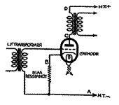
Fig. 2 shows a typical method of applying automatic bias to an indirectly heated low-frequency A.C. valve.
The circuit has been stripped of certain elaborations which are desirable in practice, but the omission will make the explanation of the principle clearer. It will
be seen that the secondary of the inter-valve transformer is connected between the grid and the common negative wire, while a resistance is connected between
the cathode of the valve and the common negative. It will be understood that if H.T.- is taken as zero potential, any point in the anode circuit of the valve will be at a
higher potential. The greatest potential difference will, of course, be between points A and D (H.T.+ and HT-). C, the anode of the valve, will be at a lower potential than D but still very positive with respect to A. B will be at a lower potential than C but still positive to A. But if B is positive to A, A must be considered negative with respect to B and, since the grid of the valve is connected back to A, and is therefore at the same potential, B is positive with respect to the grid or, in effect, the grid is negative with respect to the cathode. In other words, negative grid bias is applied automatically.
For H.F. Valves.
The amount of negative grid bias depends upon the value of the anode current flowing through the biasing resistance and the value of the resistance itself; actually the bias is equal to the voltage drop in the biasing resistance and we shall see, a little later on, how to calculate the best value. Meanwhile, however, it is first necessary to give the practical arrangements by which auto bias can best be applied to valves of various types. First of all we will deal with indirectly heated A.C. mains valves, because it is valves in this class for which the automatic bias principle is chiefly adopted.
| Fig.3 |
|
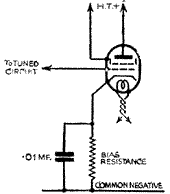
Most indirectly heated screened grid valves require a small amount of negative bias in order to prevent grid current distortion - the usual value of bias being about 1.5 volts. The method indicated in Fig. 2 is quite suitable, but it is preferable to shunt the bias resistance with a fixed capacity condenser of .01 mfd. or greater, as shown in Fig. 3.
In the case of an indirectly heated variable-mu screened grid valve, provision must be made for varying the bias for volume control purposes, and the grid bias resistance must, therefore, be a rheostat. The actual value is generally recommended by the valve maker but is usually of the order of 7,500 to 10,000 ohms for long grid base valves and, of course, correspondingly less for valves with a restricted grid base. Many valve makers recommend a special self compensating circuit for this purpose and, in any case, it is advisable to include a fixed resistance in series with the adjustable unit, its value being calculated to give the 1.5 volts or so that is necessary to avoid grid current.
| Fig.4 |
|
On the L.F. Side.
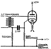
Coming, to low-frequency amplifying valves, we will take first an early stage valve -not the output valve. Here again the circuit shown in Fig. 2 is satisfactory, but should be modified as shown in Fig. 4. Here the grid circuit, instead of being connected directly to the common negative, is connected through a high resistance
of about 50,000 ohms, a condenser of from 1 to 2 mfd. being connected between the secondary of the transformer and the cathode. Those two components form a decoupling circuit very similar to that frequently employed in the anode circuits of valves. Its object is to prevent any extraneous variations, such as mains ripple, present in the high-tension supply, being passed on to the grid of the valve when, of course, it would be amplified by the valve and produce hum. This decoupling circuit is not always necessary, and listeners who are converting their sets to automatic bias might try the effect of the bias resistance by itself, adding the decoupling resistance if any considerable hum is noticed.
| Fig. 5a.- An alternative method of biasing an output valve of the indirectly heated type. |
|
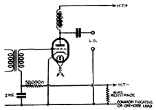
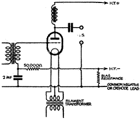
A slightly different system of automatic biasing is recommended for output valves of the three electrode type, whether indirectly or directly heated. This is shown in Figs. 5A and 5B and is so designed that the biasing resistance is not included in the output circuit of the valve. In other words, instead of connecting the grid to common negative and raising the potential of the cathode, the cathode is connected to the common negative, which is raised to a positive potential with respect to H.T. - and the grid is connected to H.T. --- By thus removing the bias resistance from the output circuit the loss of audio-frequency energy represented by the power dissipated in the biasing resistance is avoided.
| Fig.5b |
|
It will be noted that the two diagrams Figs. 5A and 5B are identical except that, in the case of the directly heated valve, the centre tap of the filament winding is connected to the common negative.
Resistance Circulation.
Indirectly heated pentode valves can, if desired, be biased in the simple manner shown in Fig. 4, because the impedance of the load in a pentode output circuit is usually high compared with the biasing resistance and the losses in the resistance are therefore not so serious. The arrangements shown in Fig. 5A, however, is preferable. Diagram 5B must, of course, be employed for, a directly heated pentode.
It must he remembered that the circuits shown in Figs. 5A and 5B are such that the who whole high-tension current of the seat, and not only the anode current of the output valve passes through the bias resistance, and in calculating the value of the resistance this face must be kept in mind. Provided the calculation is correctly made, and providing the total high-tension consumption of the set is constant, the system if perfectly satisfactory. If, however, one or more variable mu valves are employed An the high-frequency stages, their anode currents will vary according to the setting of their own biasing resistance, and this would upset the bias arrangements for the output valve.
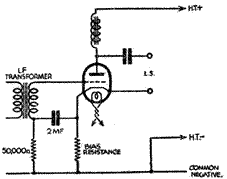
In such a case, therefore, a further variant of the biasing circuit is necessary. This is given in Fig. 6, and is similar to that shown in Fig. 4, except that the resistance is again excluded from the output circuit.
| Fig.6 |
|
Example:To find the correct bias resistance for a valve requiring a bias of 18 volts and taking 30 milliamps.
Resistance = 18 x 1,000/30.
= 600 ohms.
As it it is not always possible to obtain a fixed resistance of exactly the value required, it is an advantage to use a semi-adjustable resistor of rather higher maximum value than the correct figure found by calculation, and this will allow of a certain margin for final adjustment for best results. Some designers go farther, and use two resistances for biasing, one fixed and the other variable, connected in series. The object is to avoid running the valve. with no bias or very low bias, if, by error, the adjustable resistance is moved too far over towards its minimum position.
Taken from HOBBIES magazine issue 607 dated March 11th, 1933
Send this page address - CLICK HERE - to a friend !

