| | Roger Bleeps
CB Circuits
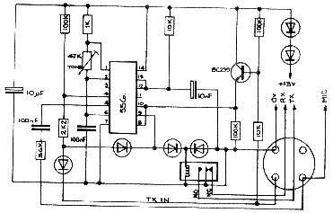
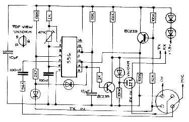
The first two circuits are very similar and use a 556 dual timer IC to produce both the bleep tone and the transmit delay function. The use of the trigger and reset pins together is an unusual feature which is used to remove the need for an extra transistor inversion stage. The use of the IC in this way has an unfortunate side effect of making it very critical of supply voltage, consequently you may need to alter the number of diodes on the 13v line in order to maintain the 556 supply at 11v to 12.5v or else fit a zener and resistor to stabilize the voltage.

The first circuit uses a miniature 12v relay for TX/RX switching, whilst the second version uses a bipolar transistor and Vmos FET combination. This version is slightly cheaper but has the drawback that on some rigs (notably Cybernet 134 board) the bleep will be heard through the speaker. Some people like that.
 Both versions require the TX input from the mic socket to go directly to the bleep circuit which provides a corresponding TX output for the rig. The RX input from the mic socket is not used in the relay version. In the second circuit the RX input is taken to the bleep board which provides an RX output to the rig. In both circuits the audio output from the bleep board is connected to the mic input wire on the socket. I think the diagrams make all this clear. Both versions require the TX input from the mic socket to go directly to the bleep circuit which provides a corresponding TX output for the rig. The RX input from the mic socket is not used in the relay version. In the second circuit the RX input is taken to the bleep board which provides an RX output to the rig. In both circuits the audio output from the bleep board is connected to the mic input wire on the socket. I think the diagrams make all this clear.
To switch the bleep off, by the way, disconnect the 10uF delay capacitor.

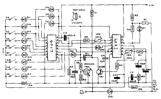
The third circuit produces a train of up to nine bleeps (although if all nine are switched in only one long continuous tone will be heard). A 4017 decade counter is used as a shift register to enable each bleep. The presence or absence of each bleep (except the first) is determined by the position of the eight DIP switches S2 to S9. (S1 is permanently closed since it is assumed that at least one bleep will be required!) A "K" for instance could be programmed by setting S2 and S3 ON, S4 OFF, S5 ON, S6 OFF, S7,S8,S9 ON. to give
- . - "da di da"
Before you get too excited I must point out that this bleep was designed for a Yaesu transceiver with internal relay switching, which limits its application to rigs with relay switching, unless you add your own relay to it.
IC2 is a quad two-input NOR IC which performs delay functions, gating functions and produces the bleep tone which is adjusted by VR3. VR2 determines the speed and VR1 the output (volume). A VN10KM Vmos FET is used to "pull" the TX line low during the bleep function. This circuit is susceptible to interference from high levels of RF radiation and should be suitably screened or kept away from the transmitter output.
| |