|
| ||
 | ||
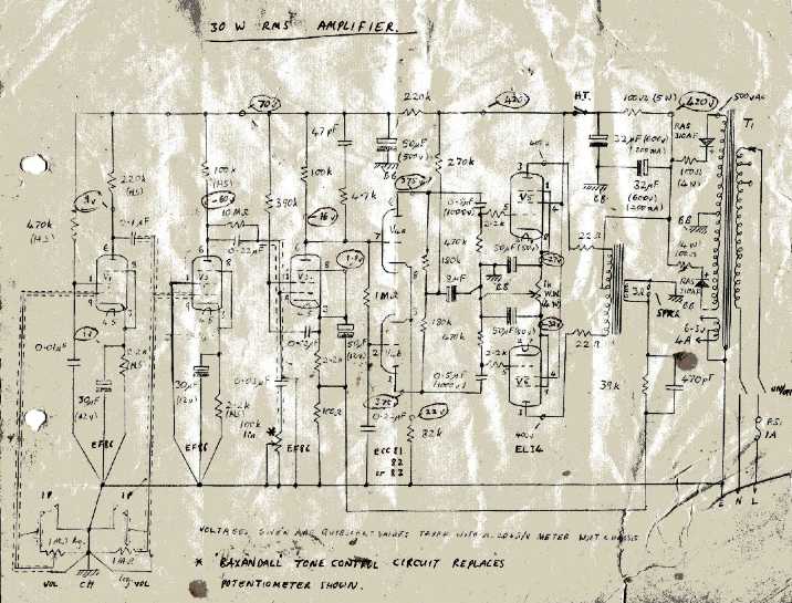
| Click on the image to open a magnified view that you can save to your computer. I'm sorry about the poor quality but I drew this diagram back in the nineteen seventies when I was a penniless student and a computer filled a room! Don't be put off by the "measly 30 watt rating". This is Watts RMS and it will be plenty loud for a small hall. The valves were common types back then and should still be obtainable now (2012). The mains transformer is a bit specialised but there are still suppliers. The output transformer will be the most expensive part but remember that I was a penniless student. I found an old 240v mains transformer with a centre-tapped secondary winding for 300-0-300 volts and valve heater windings for 6.3V, 5V and 4V. I used this as my output transformer - ignoring cries from knowledgeable engineers of "IT'LL NEVER WORK!" - and it did work. The 240v winding is not used. Leave it disconnected. I connected two of the low-voltage heater windings together (observe phase!) to provide an output to an 8 Ohm loudspeaker. I used trial and error, using the combination that produced the highest volume. The wirewound and/or high wattage resistors are a bit special. The electrolytic capacitors need to be rated at a voltage slightly higher than the working voltage on the diagram. The capacitance values are not critical. For example, you can use 33uF for 32uF , 47uF for 50 uF and you can use 10uF for 8 uF. The other capacitors are polyester film types and note that some of them need a high voltage rating, although for most of them 100v DC will be fine. The two rectifier diodes labelled "RAS310AF" can be replaced by ordinary 1N5407 or 5408 diodes. The 1K wirewound potentiometer rated at 4 watts will be expensive - IF you can even find one. I suggest you use a more ordinary 220 Ohm 1 Watt potentiometer with a 390 Ohm resistor on each side of it. It's only used to balance the output valve gains to minimise distortion so you shouldn't need the full range of adjustment. Indeed, you could probably use two 470 Ohm 2W resistors instead. The input impedance at the grids of the valves is high and susceptible to interference, so use thin, coaxial, shielded microphone cable as indicated by the dashed lines. | ||
| Send this page address - CLICK HERE - to a friend ! | ||
